For dynamically scheduled downlink traffic, useful data depends on a complete control-to-data chain:
CORESET → Search Space → PDCCH candidate → decoded DCI → PDSCH allocation → HARQ outcome
A problem can occur at any link.
The network may not select the UE. It may select the UE but fail or defer a control allocation. It may transmit PDCCH and the UE may not decode the expected DCI. Or the DCI may decode correctly while PDSCH fails or carries little data.
This is why “PDCCH congestion” cannot be concluded from stable RSRP, falling throughput or fewer UE DCI decodes alone.
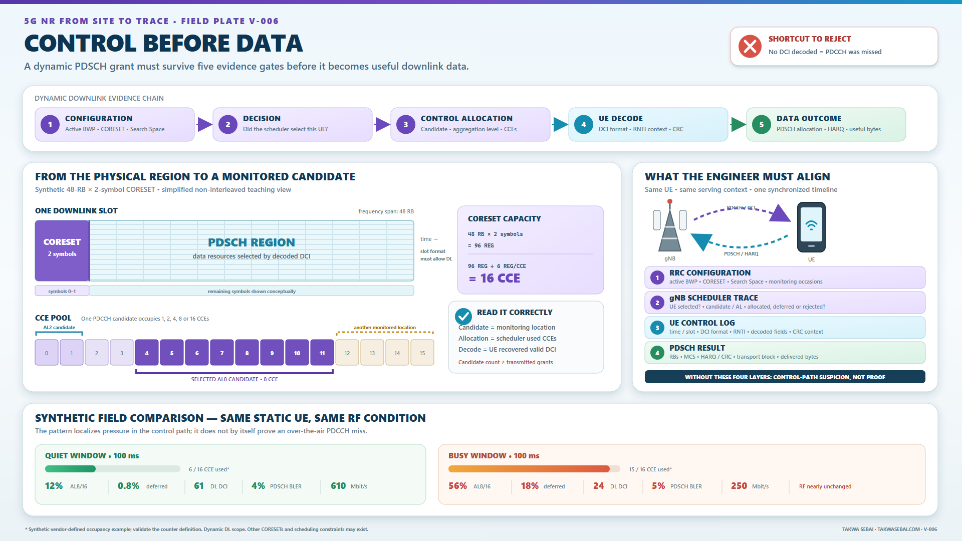
Original Takwa Sebai evidence map. CORESET dimensions, candidates, values and counters are synthetic. The plate illustrates dynamically scheduled downlink traffic, not an operator configuration.
Six questions before saying “PDCCH problem”
- Configuration: where and when should the UE monitor PDCCH?
- Scheduling decision: did the gNB select this UE?
- Control allocation: did it allocate an applicable candidate and aggregation level?
- Reception: did the UE decode the expected DCI?
- Data allocation: what resources and parameters did the DCI indicate?
- Outcome: did the UE receive useful data on the scheduled PDSCH?
If the evidence cannot answer a question, the conclusion must stop before that point.
Data can fail before the data channel
PDSCH carries downlink data and other downlink information. PDCCH carries DCI. In the common dynamic-scheduling path, the DCI identifies resources and transmission parameters that apply to PDSCH.
This creates an operational asymmetry:
- PDSCH capacity may be available;
- synchronization-signal RF measurements may look stable;
- scheduled PDSCH may decode well when it occurs;
- the UE may still receive fewer dynamic assignments than expected.
This does not automatically indicate a PDCCH fault. The scheduler may intentionally provide fewer grants because of load, QoS, policy, buffer state or another resource constraint.
Keep this rule visible:
No DCI decoded does not mean DCI was transmitted and missed.
Also identify the scheduling mechanism. Semi-persistent or other configured processes can create PDSCH occasions without a fresh dynamic scheduling DCI for every occurrence.
CORESET: the physical control container
A Control Resource Set defines a region in frequency and time where PDCCH can be mapped.
At the physical layer, a CORESET contains:
- a configured frequency resource;
- one, two or three OFDM symbols in time.
RRC represents the frequency-domain selection with a bitmap whose bits correspond to groups of six resource blocks in the applicable BWP.
The basic units are:
- REG: one resource block during one OFDM symbol;
- CCE: six REGs;
- PDCCH candidate: one possible CCE set monitored for DCI;
- aggregation level: number of CCEs in that candidate.
Supported aggregation levels are 1, 2, 4, 8 and 16 CCEs.
Synthetic calculation
Take a CORESET with:
- 48 resource blocks;
- two OFDM symbols.
Then:
48 RB × 2 symbols = 96 REG
and:
96 REG ÷ 6 REG per CCE = 16 CCE
This makes aggregation pressure tangible:
- one AL16 candidate can occupy all 16 CCEs;
- two non-overlapping AL8 candidates can occupy all 16;
- eight non-overlapping AL2 candidates can also occupy all 16.
These 16 CCEs are not the total control capacity of the cell. A deployment may use several CORESETs and Search Spaces, candidates may overlap, and monitoring occasions vary.
The candidate locations come from configuration and procedure, not from visually dividing a rectangle.
Search Space: where and when the UE looks
The CORESET defines physical resources. The Search Space defines monitoring rules for PDCCH candidates associated with those resources.
The configuration can include:
- associated CORESET;
- slot periodicity and offset;
- monitoring duration;
- first monitoring symbols in the slot;
- candidate count at each aggregation level;
- common or UE-specific type;
- monitored DCI formats.
Keep three states separate:
| State | Meaning |
|---|---|
| Search Space configured | rules exist for possible monitoring occasions and candidates |
| Monitoring occasion present | time conditions say the UE should monitor |
| PDCCH transmitted for this UE | the gNB placed encoded DCI in a candidate for the relevant context |
A configured Search Space does not mean the gNB transmits DCI at every occasion.
Candidate count is not a grant count
If a decoder shows two candidates configured at AL8, the safe statement is:
The UE can be required to monitor two configured AL8 candidates under the applicable procedure.
It is not:
Two AL8 PDCCH transmissions occurred.
Candidates are possible decode locations, not delivered grants.
Aggregation level: robustness and resource pressure
A larger aggregation level gives an encoded control message more physical resources. It can support more robust reception for a given DCI payload.
It also consumes more CCEs. Fewer non-overlapping control messages can then fit in the same physical region.
Do not turn that trade-off into a universal rule such as “cell-edge UE always uses AL16”. Selection can depend on:
- control-channel quality estimates;
- payload and DCI format;
- beam state;
- available candidates;
- scheduler implementation and policy;
- current control-resource pressure.
Candidate overlap also matters. The sum of configured candidate sizes is not the number of CCEs physically consumed. Only transmitted allocations occupy resources in a given occasion.
DCI: the message inside PDCCH
DCI formats serve different purposes. For example, DCI format 1_0 can schedule PDSCH in one downlink cell, with fields that may include:
- frequency-domain assignment;
- time-domain assignment;
- modulation and coding;
- HARQ process;
- new-data and redundancy-version information;
- feedback-related parameters under the applicable context.
The analyst must preserve:
- DCI format;
- Search Space type;
- RNTI used for CRC scrambling;
- serving and scheduling cell;
- active BWP;
- current RRC configuration;
- decoded fields;
- decoder limitations.
RNTI is part of detection
The DCI CRC is scrambled with the relevant RNTI. A successful connected-mode decode using C-RNTI supports that:
- a candidate was detected;
- CRC validation succeeded in the C-RNTI context;
- fields can be interpreted with the current configuration.
It does not count invisible failures. A tool that logs only successful DCI cannot directly measure every missed PDCCH.
Follow decoded DCI into PDSCH
The UE combines DCI with higher-layer configuration.
Time-domain interpretation provides parameters such as slot offset, start symbol, length and mapping type under the applicable table.
Frequency-domain interpretation depends on resource-allocation mode and the active BWP.
Each link needs its own evidence:
| Link | Strong evidence |
|---|---|
| CORESET to Search Space | complete current RRC configuration and active BWP |
| Search Space to candidate | monitoring occasion, candidate and aggregation level |
| Candidate to DCI | network allocation plus UE decode when available |
| DCI to PDSCH resources | decoded fields interpreted with current configuration |
| PDSCH to outcome | CRC/BLER, HARQ, MCS, layers, allocation and delivered bytes |
A decoded DCI does not guarantee successful PDSCH. Healthy PDSCH when scheduled cannot recover a missed or absent scheduling opportunity.
Four different reasons for “no data”
1. The gNB did not schedule the UE
Possible contexts:
- no applicable buffer data;
- another UE or service had priority;
- policy or QoS limited the UE;
- data resources were constrained;
- the UE was not in the expected state.
There is no missed PDCCH if no DCI was created.
2. Control allocation was deferred or rejected
The scheduler wanted to send DCI but could not allocate a valid candidate under the active CORESET, Search Space, aggregation and resource conditions.
This requires network-side evidence. Any supplier counter must be defined before it becomes part of the conclusion.
3. PDCCH was transmitted but DCI was not decoded
This normally requires synchronized network and UE evidence. A UE-only gap is ambiguous because the UE cannot log a message it failed to detect.
4. DCI decoded, but PDSCH failed or was small
Investigate:
- assigned resources;
- MCS, layers and transport-block size;
- DM-RS and beam context;
- CRC, BLER and HARQ;
- scheduler allocation;
- application and transport path.
These branches prevent “PDCCH” from becoming a generic label for low throughput.
Synthetic case: stable RF, fewer assignments
This case is synthetic. No customer trace, supplier counter or author drive test is represented.
The exercise uses:
- SA connected mode;
- n78, 100 MHz, 30 kHz SCS, TDD;
- active DL BWP containing synthetic CORESET 1;
- CORESET 1 with 48 RB × 2 symbols = 16 CCE;
- non-interleaved mapping for the exercise;
- one UE-specific Search Space monitored every slot;
- synthetic candidate configuration across AL1 to AL16;
- DCI 1_1 monitored with C-RNTI;
- continuous downlink traffic.
| Indicator | Quiet interval | Busy interval | Interpretation inside the exercise |
|---|---|---|---|
| SS-RSRP | -84 dBm | -83 dBm | level is not the differentiator |
| SS-SINR | 18 dB | 17 dB | reference quality broadly stable |
| Connected active UEs | 9 | 45 | higher control demand |
| Mean scoped CCE use | 6/16 | 15/16 | region close to full in busy interval |
| Scoped allocations using AL8/16 | 12% | 56% | more CCEs per affected control message |
| Synthetic allocation deferrals | 0.8% | 18% | network evidence of pressure |
| UE DL DCI decodes per 100 ms | 61 | 24 | fewer observed assignments |
| Mean PRBs when scheduled | 190 | 180 | individual grants remain substantial |
| PDSCH BLER | 4% | 5% | scheduled data remains healthy |
| Application throughput | 610 Mbit/s | 250 Mbit/s | fewer opportunities reduce delivery |
All names and values are pedagogical. “Mean CCE use” is not a standardised 3GPP KPI.
The teaching conclusion is:
Control-resource pressure in the scoped synthetic CORESET contributed to fewer dynamic downlink assignments during the busy interval.
It is not:
Good SINR proves PDCCH congestion.
The conclusion depends on the combined evidence: unchanged configuration, higher scoped CCE use, explicit network deferrals, fewer UE assignments, healthy scheduled PDSCH and throughput following scheduling frequency.
Lowering the aggregation level is not an automatic remedy. Insufficient control robustness could make decode performance worse.
Field workflow
Step 1: reconstruct current configuration
Collect:
- active DL BWP;
- every applicable CORESET;
- frequency bitmap, duration and mapping;
- Search Space IDs and associated CORESETs;
- periodicity, offset, duration and symbols;
- candidates by aggregation level;
- CSS/USS type and DCI formats;
- UE capability and cross-carrier context.
Do not analyse stale RRC after a reconfiguration or BWP change.
Step 2: define the scheduler question
Determine whether the gNB:
- had data or control to send;
- selected the UE;
- selected format and aggregation;
- found an applicable candidate;
- allocated and transmitted PDCCH;
- deferred or rejected allocation.
Use exact counter definitions.
Step 3: preserve UE control evidence
Where available:
- timestamp and slot;
- serving and scheduling cell;
- CORESET and Search Space;
- candidate/CCE information;
- aggregation level;
- DCI format and RNTI;
- decoded fields;
- CRC or attempted-candidate status.
Step 4: follow the assignment
For the same DCI, derive:
- scheduled slot and symbols;
- allocated RBs;
- MCS, redundancy version and HARQ process;
- new-data indicator;
- layer or rank evidence;
- transport-block size;
- CRC/HARQ outcome;
- delivered bytes.
Step 5: compare a known-good interval
Keep UE, software, cell, BWP, beam context, server, service, route and duration as constant as possible.
Then compare configuration, control demand, aggregation, allocation result, DCI rate and data outcome.
Step 6: label the conclusion
Choose one:
- not scheduled;
- control allocation deferred;
- synchronized PDCCH decode failure;
- PDSCH failure after valid DCI;
- control-path suspicion because evidence is incomplete.
Evidence checklist
- [ ] Active BWP and current RRC are known.
- [ ] CORESET resources, duration and mapping are decoded.
- [ ] Monitoring occasions are reconstructed.
- [ ] Candidate counts are not presented as grants.
- [ ] CSS and USS are not mixed.
- [ ] DCI format and RNTI are identified.
- [ ] Aggregation is tied to a real allocation or decode.
- [ ] A UE DCI gap is not called failure without network evidence.
- [ ] Scheduling decision, control allocation and reception remain separate.
- [ ] DCI is interpreted with the active configuration.
- [ ] PDSCH and HARQ outcome are synchronized.
- [ ] Load, QoS, buffer and policy are checked.
- [ ] Counter definitions and aggregation intervals are recorded.
- [ ] Synthetic values remain visibly declared.
Continue the evidence chain
- Prove the active BWP before interpreting DCI.
- Read radio quality with scheduling evidence.
- Split low throughput into testable branches.
- Read the complete 5G NR field guide.
Download the free illustrated 111-page ebook.
Technical sources
- 3GPP TS 38.211 V18.9.0, especially clauses 7.3.2.1 and 7.3.2.2. ETSI publication.
- 3GPP TS 38.331 V18.9.0,
ControlResourceSetandSearchSpace. ETSI publication. - 3GPP TS 38.213 V18.8.0, especially clause 10.1. ETSI publication.
- 3GPP TS 38.212 V18.8.0, especially clauses 7.3.1.2 and 7.3.2. ETSI publication.
- 3GPP TS 38.214 V18.9.0, especially clauses 5.1.2 and 5.1.3. ETSI publication.
KEEP THE EVIDENCE PATH