A bandwidth part (BWP) in 5G NR is a configured set of contiguous resource blocks inside a carrier. A serving cell can provide several DL and UL BWPs, while the UE has one active BWP per direction at a given instant.
That distinction matters in a trace. Finding a wide BWP in an RRC configuration proves that the region exists. It does not prove that the UE used it during the throughput test.
Direct answer
To prove the active BWP at a specific instant:
- inventory the configured downlink and uplink BWPs;
- identify the initial, first-active and default roles;
- decode the relevant RRC configuration;
- reconstruct DCI, timer, serving-cell and random-access events where applicable;
- align those events with UE or network logs;
- inspect allocation and performance from the same interval.
The configuration proves what is possible. The timeline proves what was active.
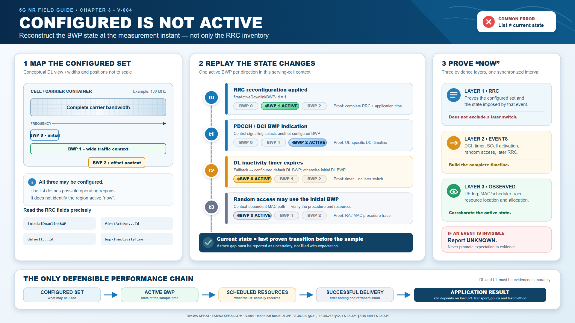
Original Takwa Sebai visual. The state changes and example values are synthetic and are used to explain the evidence workflow.
Keep the terms separate
| Term | Practical meaning | What it does not prove |
|---|---|---|
| Carrier bandwidth | Total configured carrier span | Which subset the UE is using now |
| Initial BWP | BWP used for applicable initial-access procedures | Permanent traffic state |
| Configured BWP | One possible DL or UL operating region | Current active state |
| First active BWP | BWP selected after applicable RRC configuration or activation | That it remained active later |
| Default DL BWP | Fallback-related configured role where applicable | Current state before timer analysis |
| Active BWP | DL or UL operating context at a specific instant | Performance without allocation evidence |
Downlink and uplink are separate questions. Do not assume that the same BWP identity or transition explains both directions.
What the RRC configuration can prove
RRC can expose:
- the BWP inventory;
- location and bandwidth parameters;
- common and dedicated configuration;
- initial, first-active and default identifiers;
- inactivity-timer configuration;
- serving-cell and secondary-cell context;
- parameters needed to interpret later events.
RRC alone may not prove the active state at a later measurement instant.
The active state may depend on:
- the state established after configuration;
- DCI-based BWP indication where applicable;
- inactivity-timer expiry;
- serving-cell activation or deactivation;
- random-access procedures;
- implementation and release behaviour.
Fields to locate in a decoded RRC trace
Do not stop at the presence of downlinkBWP-ToAddModList. Keep the identifiers, direction and application time together.
| Decoded field | What it contributes | What remains unproven |
|---|---|---|
initialDownlinkBWP / initialUplinkBWP |
Initial common operating context | The later traffic BWP |
downlinkBWP-ToAddModList / uplinkBWP-ToAddModList |
Dedicated BWP inventory and identifiers | Which entry was active at the test instant |
firstActiveDownlinkBWP-Id / firstActiveUplinkBWP-Id |
State selected when the applicable configuration takes effect | Whether a later switch occurred |
defaultDownlinkBWP-Id |
Configured fallback-related DL role | That the fallback timer expired |
bwp-InactivityTimer |
Timer configuration used in the state reconstruction | The observed start, restart or expiry event |
The decoded structure supplies the possible state transitions. DCI, MAC events, timers and aligned logs carry that state to the measurement instant.
What DCI and MAC evidence add
When a BWP indicator is present and applicable, DCI can support a transition or selection on the timeline.
MAC and serving-cell procedures may add evidence about:
- inactivity-timer behaviour;
- random-access state;
- cell activation;
- the context in which a BWP change applies.
Do not search for one universal “active BWP message.” Build the state from the applicable procedure.
Build the BWP timeline
Use a table like this:
| Time | Evidence | Proven state | Remaining uncertainty |
|---|---|---|---|
| T0 | RRC configuration decoded | BWP set and roles known | Later active state unknown |
| T1 | First-active identifier applies | Initial post-configuration state supported | Duration unknown |
| T2 | Applicable DCI indication | New BWP state supported | UE decode and later transitions |
| T3 | Inactivity timer expires | Default-related transition may apply | Exact implementation evidence needed |
| T4 | Throughput sample | Performance observed | Active state must be carried from prior evidence |
Every conclusion should state the interval over which it remains valid.
Synthetic diagnostic case
This scenario is synthetic and contains no customer trace.
Configuration:
- a carrier contains several configured BWPs;
- one wide dedicated BWP is available for traffic;
- a default downlink BWP is configured;
- an inactivity timer applies.
Incomplete conclusion:
“The UE was using the wide BWP during the low-throughput sample.”
Missing evidence:
- no applicable DCI event is shown;
- the timeline does not prove whether the timer expired;
- no UE or network state confirms the active BWP at the sample;
- allocation and performance are not aligned to the claimed state.
Correct conclusion:
“A wide BWP is configured, but the active downlink BWP at the throughput instant is not proven by the available evidence.”
That conclusion is less dramatic and more defensible.
Common field mistakes
Mistake 1: reading a configured list as a state
Why it fails:
- the list describes possible regions;
- the UE uses one applicable active context at an instant;
- later events may change that state.
Mistake 2: using a throughput graph without the BWP timeline
Why it fails:
- the graph shows the result;
- it does not identify the active BWP;
- the result may also depend on PRBs, MCS, layers, load, RF, transport and policy.
Mistake 3: analysing only downlink
Why it fails:
- uplink configuration and active state may differ;
- the traffic problem may be direction-specific;
- random-access and control evidence may matter differently.
Mistake 4: assuming the default BWP is always active
Why it fails:
- “default” is a configured role;
- the state still depends on the applicable transition history;
- configuration labels do not replace timeline evidence.
Field workflow
Step 1: inventory the carrier
Record:
- band and channel bandwidth;
- duplex mode;
- serving-cell identity;
- configured DL and UL BWP identifiers;
- location and bandwidth fields;
- common and dedicated parameters.
Step 2: map the configured roles
Identify:
- initial BWP;
- first-active DL and UL BWP;
- default DL BWP;
- dedicated BWP set;
- inactivity timer;
- applicable serving-cell procedures.
Step 3: rebuild the state transitions
Inspect:
- RRC application time;
- applicable DCI;
- timer start, restart and expiry;
- cell activation and deactivation;
- random-access events;
- UE and network state logs.
Step 4: align the performance window
From the exact same interval, collect:
- grants and PRB allocation;
- scheduling frequency;
- MCS and layers;
- BLER and HARQ;
- throughput measurement point;
- RF and load context.
Step 5: test a competing explanation
Ask:
- Would throughput remain low with the expected BWP active?
- Is allocation low even inside a wide active BWP?
- Does the problem follow load, RF, path or policy instead?
Minimum evidence package
- [ ] Band and carrier bandwidth.
- [ ] Configured DL and UL BWP inventory.
- [ ] Initial, first-active and default roles.
- [ ] RRC configuration and application time.
- [ ] Applicable DCI evidence.
- [ ] Inactivity-timer chronology.
- [ ] Serving-cell and random-access events where relevant.
- [ ] Active state at the exact test interval.
- [ ] Allocation and radio outcome.
- [ ] Throughput with a named measurement point.
Field stop rule
A configured BWP proves a possible operating region. It does not prove the region used by the UE at the measured instant.
Continue the workflow
- See how numerology and bandwidth constraints interact.
- Follow control from PDCCH to PDSCH.
- Use the low-throughput diagnostic tree.
- See how real and synthetic evidence is labelled in the RAN Evidence Lab.
Read or download the complete field guide.
Public technical references
- ETSI TS 138 300 V18.9.0, clause 6.10.
- ETSI TS 138 213 V18.8.0, clause 12.
- ETSI TS 138 321 V18.9.0, clause 5.15.
- ETSI TS 138 331 V18.9.0,
ServingCellConfig,BWP-DownlinkandBWP-Uplink.
KEEP THE EVIDENCE PATH