The useful first question is:
At which phase did mobility stop, and what evidence proves it?
In NSA, NR can be added, modified, changed, deactivated or released while the LTE Master Node remains. In SA, the UE can complete radio access at the target before core path switching and source-context release are finished.
These are different procedures with different messages and failure boundaries.
The field method is:
- name the architecture and procedure;
- map source, target, Master Node and Secondary Node identities;
- separate preparation, command delivery, target access and completion;
- preserve evidence at each boundary;
- stop the diagnosis where the evidence stops.
A missing message locates the next boundary to test. It does not name the physical root cause.
Not every visible transition is a handover
| Visible change | What may actually be happening |
|---|---|
| Serving beam changes | lower-layer beam management inside one cell |
| NR appears while LTE remains | EN-DC Secondary Node or SCG addition |
| NR PSCell changes while LTE anchor remains | PSCell change or Secondary Node procedure |
| NR disappears while LTE remains | SCG deactivation or Secondary Node release |
| NR PCell changes in SA | intra-NR handover or another mobility procedure |
Record:
- mode: LTE, EN-DC, another MR-DC mode or SA;
- core: EPC or 5GC;
- control-plane anchor;
- Master Cell Group PCell;
- Secondary Cell Group PSCell, if configured;
- before/after cell identities;
- procedure name supported by messages;
- interface carrying each network message.
A throughput interruption during NR release in EN-DC is not automatically an LTE handover failure. A beam change is not automatically a cell handover. A source-to-target RRC command does not prove target access.
EN-DC: LTE remains the Master Node
In EN-DC with EPC, the UE connects to:
- an LTE eNB acting as Master Node;
- an en-gNB acting as Secondary Node.
The eNB connects to EPC over S1 and to the en-gNB over X2.
The functional roles matter:
- LTE PCell belongs to the Master Cell Group;
- NR PSCell belongs to the Secondary Cell Group;
- the Master Node provides the control-plane connection;
- the Secondary Node provides additional radio resources;
- initial Secondary Node RRC configuration reaches the UE through the Master Cell Group signalling path.
The Master Node is not the cell with the strongest reference signal. It is a control-plane role.
If LTE remains the same Master Node while NR is added, changed or released, do not label the event as an LTE anchor handover.
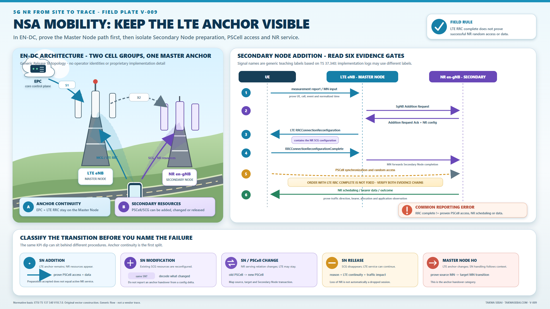
Original Takwa Sebai EN-DC evidence flow. It is a generic Release 18 teaching sequence, not an operator trace.
EN-DC Secondary Node addition: six gates
Gate 1: Master Node decision
Evidence may include:
- active LTE measurement configuration;
- UE MeasurementReport on the LTE signalling path;
- Master Node admission or decision record;
- UE and bearer context;
- X2 connectivity and intended Secondary Node.
A measurement report is an input, not proof that NR resources were requested.
Gate 2: Secondary Node preparation
The Master Node sends an addition request. If admitted, the Secondary Node selects and prepares the PSCell and resources, then returns an acknowledgement containing the NR RRC configuration.
At this boundary, ask:
- was the request sent to the intended node?
- was it accepted or rejected?
- which PSCell and frequency were selected?
- what NR configuration was prepared?
- were bearer and user-plane resources admitted?
No UE-side NR access has happened yet.
Gate 3: NR configuration delivered through LTE
The Master Node sends LTE RRC reconfiguration carrying the NR configuration.
Preserve:
- outer LTE RRC transaction;
- embedded NR configuration;
- target PSCell and frequency;
- SCG state;
- random-access resources where present;
- bearer mapping;
- UE and Master Node timestamps.
If the decoder exposes only the outer LTE message, the analyst cannot safely claim that the expected NR configuration was present.
Gate 4: UE reconfiguration response
The UE responds through LTE, and the Master Node informs the Secondary Node.
This proves that the RRC procedure reached its response boundary.
It does not prove NR PSCell random access or NR user-plane delivery.
Gate 5: PSCell synchronization and random access
When active SCG resources are configured, the UE synchronizes to the PSCell and performs random access.
The order between the LTE RRC response and SCG random access is not fixed in the way a simplified call-flow diagram may imply. Successful SCG random access is not required for successful completion of the LTE RRC reconfiguration procedure.
Therefore:
LTE RRC reconfiguration complete is not equivalent to NR radio access complete.
Look for:
- target NR synchronization;
- PRACH and response evidence;
- timing advance where exposed;
- PSCell MAC activation;
- NR PDCCH/PDSCH or PUSCH;
- SCG failure information.
Gate 6: NR service outcome
Only after configuration and access evidence should the report evaluate:
- NR bearer state;
- scheduling;
- delivered NR bytes;
- bearer behaviour;
- user-plane update where applicable;
- application throughput and interruption.
An NR icon is not evidence of delivered NR service.
Name the actual EN-DC procedure
Do not merge these into one KPI called “5G handover”:
- Secondary Node addition;
- modification;
- release;
- change;
- PSCell change;
- inter-Master Node handover with or without Secondary Node handling.
The report should identify which node changed, whether only the PSCell changed, whether SCG was active or deactivated, and whether random access was required.
SA handover: three phases plus a service post-check
For a basic Xn-based intra-NR handover:
- preparation;
- execution and target access;
- completion and path switch;
- post-handover service verification.
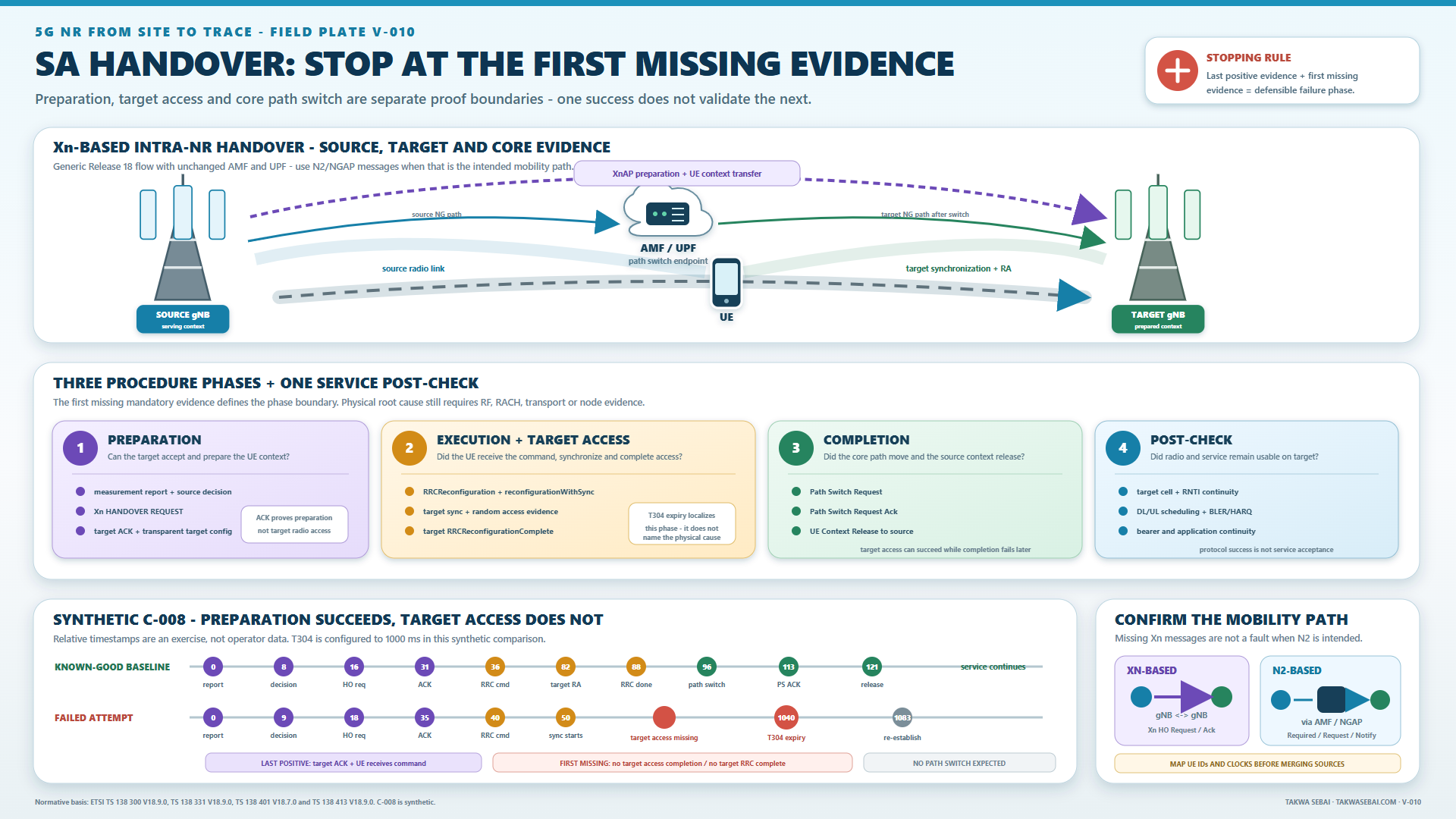
Original Takwa Sebai Xn-based SA handover map. The success baseline and failed timestamps are synthetic. The visual localises evidence boundaries; it does not identify a physical cause.
Phase 1: preparation
The basic chain is:
- source configures measurements;
- UE sends MeasurementReport;
- source makes a handover decision;
- source sends HANDOVER REQUEST;
- target performs admission and preparation;
- target returns HANDOVER REQUEST ACKNOWLEDGE with a transparent RRC container.
Preparation succeeds only when the target accepts and returns usable configuration.
Failure evidence may include:
- no source decision;
- wrong target identity;
- request not sent;
- Xn path failure;
- target rejection;
- resource, slice or QoS rejection;
- absent or unusable acknowledgement;
- explicit network cause.
UE trace alone normally cannot prove all network-side preparation states.
Phase 2: command delivery and target access
After preparation, the source sends RRCReconfiguration containing the target information. The target change is represented through reconfigurationWithSync; the UE starts T304 and synchronization toward the target.
Keep these states separate:
- source sent the intended command;
- UE decoded the intended transaction;
- target identity and
reconfigurationWithSyncwere present; - UE started target synchronization;
- target random access was attempted;
- target access completed;
- UE sent RRCReconfigurationComplete with target configuration;
- target observed and accepted completion.
“Command sent” is not “command decoded”. PRACH transmitted is not random access completed. Target RRC completion is not path switch completed.
T304 expiry localises a reconfiguration-with-sync failure. It does not identify the physical cause.
Phase 3: path switch and source release
After successful target access:
- target sends PATH SWITCH REQUEST;
- the 5GC switches the downlink path;
- the AMF sends PATH SWITCH REQUEST ACKNOWLEDGE;
- target sends UE CONTEXT RELEASE to source;
- source resources can be released.
Check:
- request sent or absent;
- AMF response and cause;
- accepted and failed PDU sessions;
- new NG-U state;
- forwarding or end-marker evidence where exposed;
- source context release;
- duplicate or stale context;
- post-handover data continuity.
Target RRC completion without path-switch evidence is not a closed handover record.
Phase 4: service verification
Protocol flow can complete while service remains degraded.
Check:
- target cell and beam stability;
- RLF or re-establishment after completion;
- PDCCH/PDSCH and PUSCH;
- BLER, HARQ, rank and allocation;
- RLC/PDCP continuity;
- delivered bytes and packet loss;
- voice or application interruption;
- source resources actually released;
- ping-pong or immediate fallback.
Protocol success and service success are separate.
Xn-based and N2-based flows expose different messages
Confirm the path before searching for a missing XnAP message.
In an Xn-based flow:
- gNBs exchange preparation directly;
- 5GC participates in path switch;
- source and target XnAP UE identifiers must be mapped.
In an N2/NG-based flow:
- source sends HANDOVER REQUIRED toward AMF;
- AMF initiates target allocation through HANDOVER REQUEST;
- target returns acknowledgement or failure;
- AMF returns the command toward source;
- target sends HANDOVER NOTIFY after target identification and completion.
The absence of Xn HANDOVER REQUEST is not a preparation failure if N2 was intended.
Preserve:
- source and target node and cell IDs;
- PCI and ARFCN;
- old and new C-RNTI;
- XnAP UE IDs;
- AMF and RAN NGAP UE IDs;
- RRC transaction;
- UE trace identity and clock.
Without identity mapping, two UEs or attempts can be merged into one false flow.
Synthetic SA case: preparation succeeds, target access does not
This exercise is synthetic. It contains no operator trace, customer identity or author incident.
Scope:
- SA connected mode;
- intra-frequency Xn handover;
- same AMF and UPF;
- no DAPS or conditional handover;
- normalized gNB and UE clocks;
- configured T304 of 1000 ms inside the exercise.
Known-good baseline
| Time | Evidence |
|---|---|
| 0 ms | MeasurementReport received at source |
| 16 ms | HANDOVER REQUEST sent |
| 31 ms | ACKNOWLEDGE received |
| 36 ms | command with reconfigurationWithSync decoded |
| 82 ms | target random access completed |
| 88 ms | target received RRCReconfigurationComplete |
| 96 ms | PATH SWITCH REQUEST sent |
| 113 ms | path-switch acknowledgement |
| 121 ms | source received UE CONTEXT RELEASE |
Failed attempt
| Time | Evidence |
|---|---|
| 0 ms | MeasurementReport received |
| 18 ms | HANDOVER REQUEST sent |
| 35 ms | ACKNOWLEDGE received |
| 40 ms | intended command decoded by UE |
| 50 ms | target-access activity begins |
| 214 ms | more activity; no completed target RRC transaction |
| 1040 ms | synthetic T304 expiry |
| 1083 ms | RRCReestablishmentRequest on recoverable source |
Absent:
- target RRCReconfigurationComplete;
- path-switch request and acknowledgement;
- source context release;
- target user-plane delivery.
What this proves:
- preparation succeeded;
- command delivery succeeded;
- execution began;
- target completion was not reached;
- T304 expired and the UE initiated recovery.
Defensible classification:
Synthetic failure during execution or target access after successful preparation and command delivery, before target RRC completion and core path switch.
What this does not prove is why target access failed. Hypotheses such as downlink synchronization, uplink coverage, RACH resource, target beam, response, configuration or UE behaviour still need discriminating evidence.
Failure matrix
| Last positive evidence | First missing evidence | Phase | Next check |
|---|---|---|---|
| MeasurementReport | source decision | pre-preparation | event validity, policy and target eligibility |
| Handover request | acknowledgement or reject | preparation | path, admission and cause |
| Acknowledgement | command at UE | source delivery | RRC transaction, scheduling and UE decode |
| Command decoded | target access completion | execution | T304, sync, RACH and target UL/DL |
| Target RRC complete | path switch | completion | NGAP, PDU sessions, AMF/UPF and transport |
| Path-switch ACK | source release | cleanup | release trigger and source context |
| Protocol complete | healthy service | post-check | RF, scheduler, RLC/PDCP, transport and application |
Use the narrowest classification supported by the last positive and first missing evidence.
Compare with a known-good flow
Keep constant where possible:
- UE and software;
- source and target;
- frequency and bandwidth;
- measurement configuration;
- service and QoS;
- route direction and speed;
- clock normalization;
- Xn or N2 procedure;
- network software and configuration.
Compare by phase, not by one total “handover time”. Supplier counters may use different start and stop boundaries.
Evidence checklist
- [ ] Architecture and core are named.
- [ ] Master Node, Secondary Node, source and target are explicit.
- [ ] PCell and PSCell identities are mapped.
- [ ] Procedure is named from messages.
- [ ] Xn and N2 are distinguished.
- [ ] Clocks and UE-associated identifiers are normalized.
- [ ] Measurement report is not called a decision.
- [ ] Preparation request, response and cause are preserved.
- [ ] Target container and UE command belong to the same attempt.
- [ ] Command, target sync and random-access completion remain separate.
- [ ] Target RRC completion is confirmed where possible.
- [ ] Path switch, PDU sessions and source release are checked.
- [ ] RLF, re-establishment and fallback are checked.
- [ ] Protocol and service outcome are evaluated separately.
- [ ] Last positive and first missing evidence are stated.
- [ ] Synthetic values remain visibly declared.
Continue the evidence chain
- Separate SSB measurement from beam state.
- Read radio measurements with traffic evidence.
- Use the low-throughput diagnostic tree.
- Read the complete 5G NR field guide.
Download the free illustrated 111-page ebook.
Technical sources
- 3GPP TS 37.340 V18.7.0, especially clauses 3.1, 4.1.2, 4.2.1 and 10.2 to 10.7. ETSI publication.
- 3GPP TS 38.300 V18.9.0, especially clause 9.2.3.2.1. ETSI publication.
- 3GPP TS 38.331 V18.9.0, especially clauses 5.3.5.3, 5.3.5.5.2 and 5.3.5.8.3. ETSI publication.
- 3GPP TS 38.401 V18.7.0, especially clause 6.4. ETSI publication.
- 3GPP TS 38.413 V18.9.0, especially clauses 8.4.1 to 8.4.4. ETSI publication.
KEEP THE EVIDENCE PATH